At the end of step 2 we came to the conclusion that a clean and normalized version of the upper part would be required, which then could enable us to examine further the triplets' connection to each other after the three rotations. Hence, in this step we will sort out the items we are interested in, and place them in a coordinate system appropriate for performing the rotations (and for the following operations as well).
Creating the coordinate system is the easier part of the task. We will simply use a two dimensional system with its origin placed at the center of the upper part, the X coordinates increasing to the right and the Y coordinates to the top:
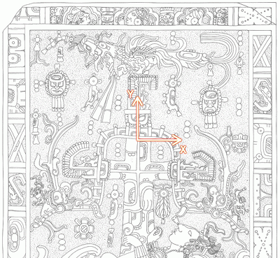
Note: at some steps we will also use the third dimension temporarily, but for the layout of the items the Z coordinate is not necessary.
As to choosing the appropriate items and placing them properly in the system, the situation is a bit more complicated. Such processes usually require more iterations, and only at a later stage will become definitely certain (or at least probable), that we made the right decisions previously. Here, in case of the Palenque code, the control phase at step 7 will provide us such an opportunity to check our starting layout, and, according the picture there, we must potentially come back to this step, rearrange some items and then perform the operations again, and so on, until all elements are placed in a satisfactory way.
It would not make much sense to go through the entire iteration process here, and so I only present the layout that I have found to be the most suitable one. However, a separate (Java) application was created (PalenqueLayout), that you can use to test this and other arrangements, and, after performing the steps up to the control phase and inspecting the corresponding end result you can form your own opinion about the layout presented here and the decisions made at this step. (For further information about the application and its usage please refer to the page describing it).
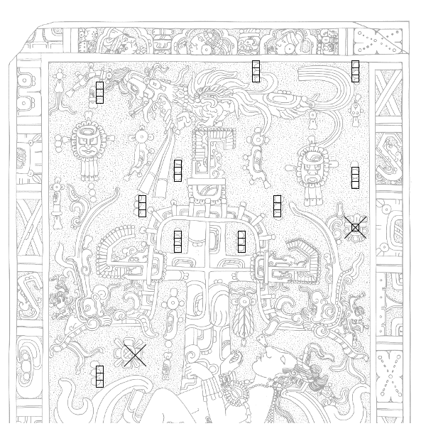
From among the triplets we will use all, except those two that already played their roles in the previous step (as parts of the diagram of the Solar System). Additionally, considering the message we expect from solving the code (the location of the other system), we would also need of course a representation for the stars of the two solar systems. If we take a look at the lid, we can find two starlike symbols that seem to be there for this exact purpose, and their positions (left / right side) determine unambiguously, which solar system they belong to:
Now we have every information to choose the items for the arrangement. Here you can see them marked with their respective reference numbers (the numbers were arbitrarily defined, and serve only the purpose of referring to the elements):
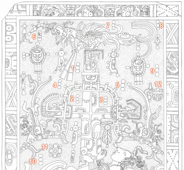
Note: About the issue with item #6, whether it should be treated as a triplet or not, you can read more here. Long story short: initially, due to the sketchy drawing I considered it to be a triplet, and, because of its size and position, I personally am inclined even now to believe that it should have been a triplet, but was carved wrongly. However, the matter has no real relevance, as the items at the corners (#6, #8, #10) play only a subordinate and temporary part during the solution. By the way, it is obvious that the craftsmen who actually carved the lid had absolutely no idea of any hidden code in the drawing, as the pattern is full of issues in this regard: the triplets have different sizes, they are not arranged vertically, etc. The iterations between this step and the control phase are mostly needed to compensate for these inaccuracies introduced by the careless carving.
After placing the items in the coordinate system we finally get the layout:
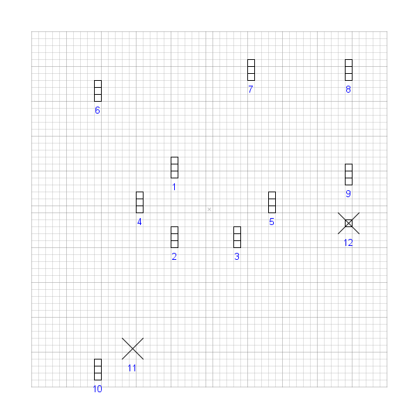
The following table shows the exact coordinates for each item (the triplets measure 1×3, the two stars 3×3, and all coordinates apply to the center subelement):
| # | Type | X | Y |
|---|---|---|---|
| 1 | T | −5 | 6 |
| 2 | T | −5 | −4 |
| 3 | T | 4 | −4 |
| 4 | T | −10 | 1 |
| 5 | T | 9 | 1 |
| 6 | T | −16 | 17 |
| 7 | T | 6 | 20 |
| 8 | T | 20 | 20 |
| 9 | T | 20 | 5 |
| 10 | T | −16 | −23 |
| 11 | S | −11 | −20 |
| 12 | R | 20 | −2 |
Note: you can use the PalenqueLayout application
to export these data in XML, CSV or other formats.
The import code for this layout:
PQLT9506T9596T0496T9001
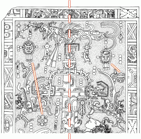
Superimposing the normalized layout over the original images reveals the type and amount of correction that was necessary to compensate the carving inaccuracies:
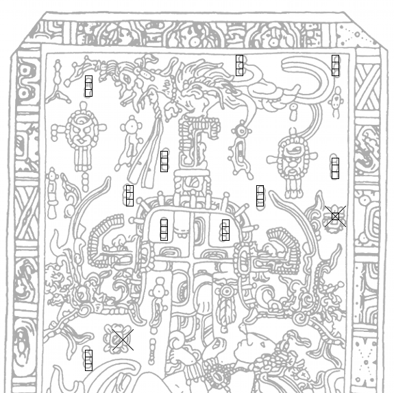
In this step we have successfully constructed a cleaned and normalized version of the upper part. Using that we will be able to perform the three rotations again, but this time without the distracting superfluous elements at last.